30FXC Transmitter
Copyright CCA 2013
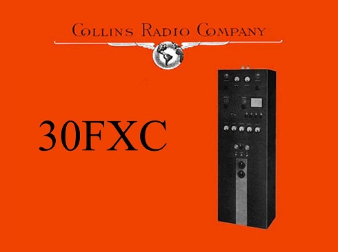
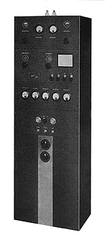
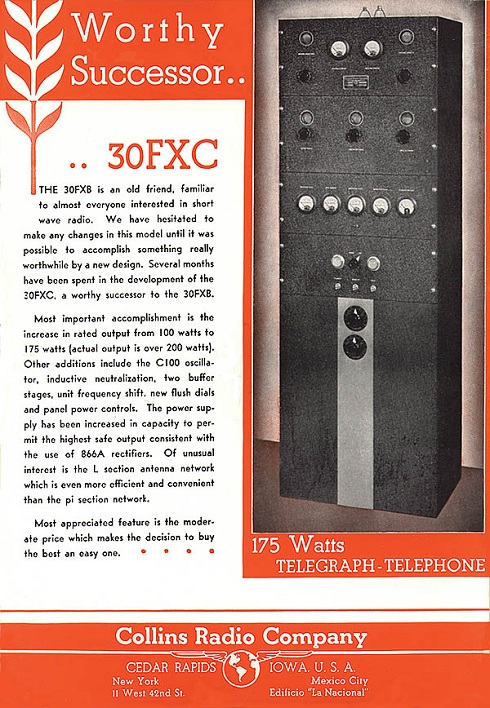
The 30FXC was introduced in 1936 as the successor to the popular 30FXB phone/cw transmitter. It was rated at 175 watts (but proudly boasted of over 200 watts) output on AM and CW, and covered 1500 to 30,000 kHz.
During this period Collins was being sued, and enjoined, by RCA, AT&T, Westinghouse, and others (known as the “Radio Trust”) over Collins’ use of certain circuits which employed patents owned by this trust. These patents had been earlier purchased from deForest. Also at issue was the basic deForest triode oscillator circuit patent controlled by RCA.
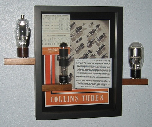
As a response, Collins partnered with Amperex to produce and brand its own tubes which employed a novel grid structure. The workaround on the critical oscillator patent was for Art Collins to secure the patent rights from Dr. Robert Goddard (of liquid fuel rocket fame) who had been granted a patent on his unusual external grid vacuum tube in 1915. Collins developed its own oscillator circuit around this unique tube having its grid on the outside of the glass envelope. Produced by Amperex and branded the C100A, this tube was actually somewhat quirky in its operation and likely required component value “tweaks” to ensure reliable operation. Today the Collins C100 series tubes are among the rarest collectable Collins tubes.
The C100A and the C100D were the only production versions of this unusual tube with the B and C being prototypes. Below center is a rare C100A and on the right is a C100D (photo K0CXX.org).
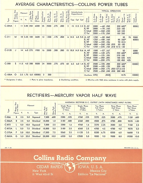
Below – Offering of Collins tubes in rare Collins 1936 Tube Brochure.
In the 30FXC the C100A drove a single 46 frequency multiplier, or a second cascaded 46 multiplier, depending on desired operating frequency. An RK20 intermediate amplifier drives the power amplifier tube, a Collins C201.
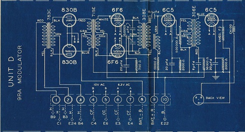
The speech amplifier was built on the modulator chassis and was designed to accept the recently introduced crystal microphone (a D-104). The modulators were RK31s (830Bs were alternates) operated class B.
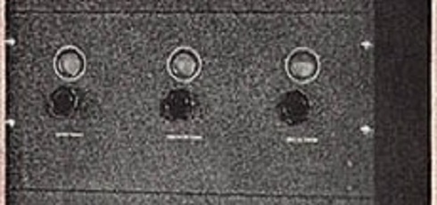
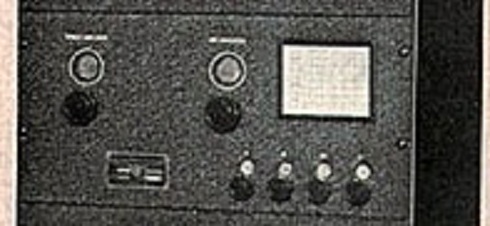
The 30FXC used a total of 7 flush mounted panel meters. Two RF ammeters at the top were recessed from the front panel to reduce shunt capacity across the transmission line for more efficient operation at 30 mHz. The remaining five meters spanned the width of the transmitter just below the RF chassis and provided convenient monitoring of all critical current or voltage values.
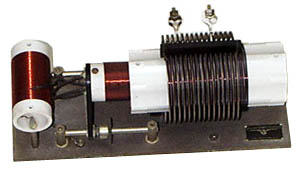
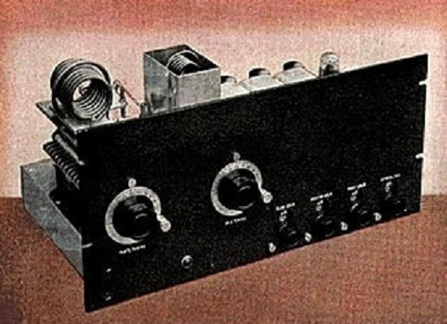
Plug-in coils were used for each band. The final tank assembly was a variation of the 45A final tank coil assembly. Instead of the double-duty driver/inductive neutralization coil, a separate driver and neutralization coil were used. As with the 45A, the entire assembly was mounted on an Mycalex base. The 30FXC was 55″ high, 13″ deep, 19″ wide, and weighed 260 pounds. It was finished in black winkle enamel paint on the exterior and smooth aluminum paint on the inside. A special upgrade RF section, the 10X, was offered for improved performance on the higher frequencies of 27 MHz and above. In fact, there were three different RF sections associated with the 30FXC. Initially the unit was introduced with an early version of the 10M exciter/final deck. This is pictured below.
By May of 1936, the RF section design was changed to the more well know 10M (Below).
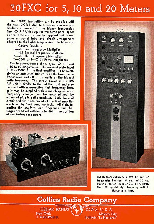
This RF deck was carried through to the close of production and touted as a 1.5 to 30 mHz transmitter deck. In fact, the performance of the 10M deck on 10 meters was marginal and Collins began offering the 10X (10 to 60 mHz) RF exciter/amplifier deck along with the standard 10M. The 10X RF unit was first promoted in December of 1936.
In addition to the variants of the RF deck described above, Collins also started offering the 30FXR in July of 1936. The FXR was nothing more than a 30FXC without the balanced coupler and with a reduction in capability of the amplifier HV plate transformer. This allowed Collins to sell the FXR for a reduced price and still advertise that it could be upgraded at any time. Obviously Collins was getting some significant static from their potential customers about the price of the 30FXC.
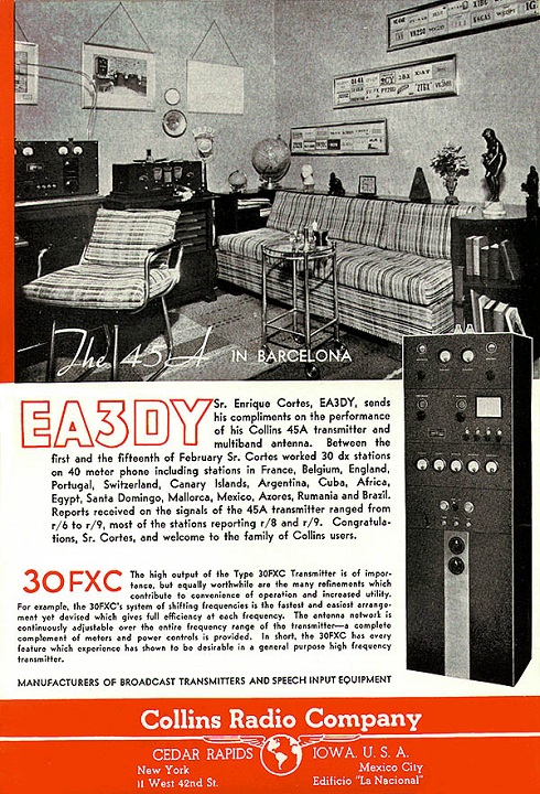
Below are the advertisements that appeared throughout 1936 as Collins went through these changes. The last ad shows the tube lineup of the 10X.
QST, February of 1936 – Showing Early Exciter/PA deck
QST, May of 1936 showing the 10M Exciter Deck
QST, December of 1936 – Offering the optional High Frequency 10X Exciter/PA Deck
Some Detailed Photos: For those of you seriously involved with a 30FXC, some rare detail photos are offered here.
Collins 9RA Modulator – Schematic
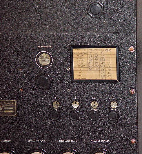
RF Deck Tuning Chart Example
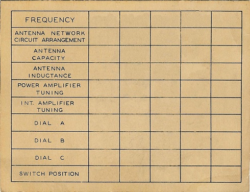
Blank 30FXC Tuning Chart
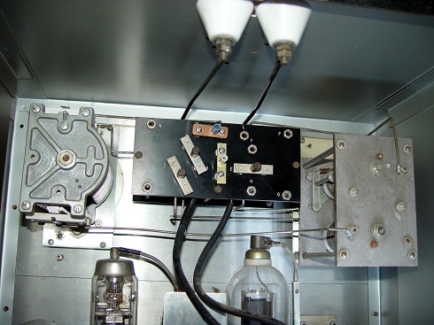
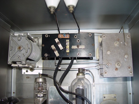
Rear Views of Balanced Line Coupler
– – – – – – – – CCA – – – – – – – –
Note: The images and text used in these pages are copyright 2012 protected, are restored and written by the Collins Collectors Association or its representatives, and may not be used in any other commercial or website applications. They may be downloaded and used privately – not for publication or internet use.
- CCA COLLINS HISTORICAL ARCHIVES
- The Pre War Years
- 150 Series Transmitter
- 2A, 2B AND 2C TUNERS (ATU)
- 30FX Transmitter
- 30FXB Transmitter
- 30FXC Transmitter
- 30FXR Transmitter
- 30J Transmitter
- 30W Transmitter
- 32 A/B Transmitter
- 32F Transmitter
- 32G Transmitter
- 40A/B Transmitter
- 45A Transmitter
- 4A Transmitter
- Bulletin 100
- Bulletin 101
- Bulletin 105
- Bulletin 200
- Bulletin 200A
- The Lost Decade
- The War Years
- Post War Broadcast / Commercial
- The Black Boxes
- The Grey Boxes
- The “S” Word or Solid State
