The 30J QSO
By Gary Halverson, WA9MZU 503 Jessica Ct. Mokelumne Hill, CA 95245 and J.B. Jenkins, W5EU 1380 Bryson Midlothian, TX 76065This is the story of the acquisition and restoration of two versions of Collins’ last prewar transmitter, one a late production (Gary’s) and the other an early production (J.B.’s). The elegant 30J is among the rarest of the Collins prewar AM transmitters.
Art’s Beautiful Baby ( Gary left & J.B. on the right )
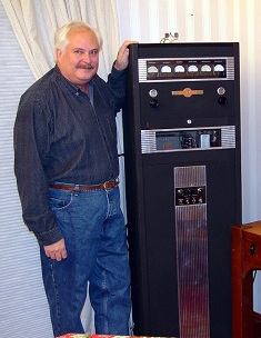
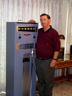
“It’s Our Baby and We Love It” was the headline over Collins’ inside cover ad in the November 1937 issue of QST magazine. Surrounded by a pretty pink background, the 30J was a stunning new design that set the high water mark for styling and performance of all the Collins prewar transmitters. The ad continues: “Like all proud parents, we could go on and on, but a glance at the specifications will show you that we are not unjustly proud.”
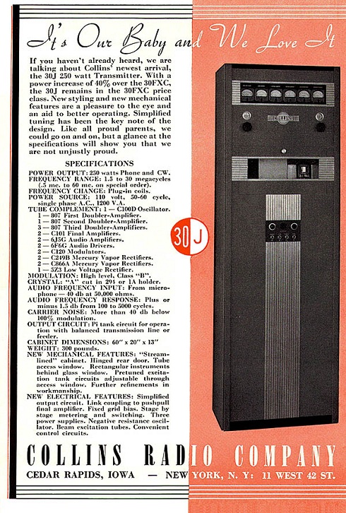
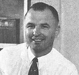
Replacing the aging 30FXC, the 30J offered a 40% power increase, a new “streamlined” cabinet, hinged rear door, a tube access window, and rectangular panel meters set behind glass – all firsts for a Collins transmitter. Personally, we believe that of all the post-war Collins AM transmitters, only the 30K series was runner-up to the 30J’s elegant Deco styling. The 30J was a general purpose transmitter “designed for general applications such as police service, aeronautical ground stations, or general purpose point-to-point communica¬tion where service is intermittent” – perfect for the discriminating amateur. The 30J was rated at 250 watts out on phone and CW. Its audio response was rated at an impressive plus or minus 1.5 dB from 100 to 5000 Hz. Carrier noise rated at more than 40dB below 100% modulation. Of particular interest is that while the 30J followed the 30FXC, which was introduced in 1936, its styling is dramatically different. So different, in fact, that (in my opinion) there has never been a prettier Collins transmitter. My guess is that as part of Collins’ strategy in making a serious effort to gain more broadcast market share, they engaged an industrial designer to do an across-the-board product facelift. The 30J was in the right place at the right time. Its distinct Deco influence can also be seen on the Collins broadcast audio mixers and transmitters from about 1936 to 1938. Two basic production runs were built, differing mainly in the tube lineups. You may recall that the use of the Collins/Goddard C100A was a legal workaround of the RCA patent on the conventional crystal oscillator, which RCA refused to license to Collins. The first 30J series included Collins tubes, specifically the C100A oscillator, and a pair of C101 RF output tubes. The RF deck was a ground-up new design using the 7000 series plug in coils later employed in the 32RA in the low-level RF stages. The driver stage, a pair of 807’s, used a plug-in shielded box to house the driver tank coils. The output tuning chassis was also a radical departure from any previous version. Designed for low induc¬tance and capacitive interaction with the plug-in tank coils, the entire frame was constructed from cast aluminum. It was mounted directly above the RF deck and provided easy access to plug-in coils, which were wound on 2.5” by 6” coil forms. The standard output was bal¬anced, but a phasing coil option could be added to convert the output to unbalanced. By about 1938 or ‘39 a patent and licensing issue with RCA had been resolved and the 30J RF deck under¬went a minor redesign to use more main¬stream tubes including the 802 in the oscillator to replace the C100D and a pair of 813’s to replace the C101 finals. This last production run was designated the 30J-18. The 30J-18 used an 802 crystal oscillator stage feeding either an 807 frequency multiplier, or a pair of 807 buffers (selectable), which drove the push-pull 813s. The same plug-in coils as the first production units were used to set the desired frequency range, then tuned with trimmers or sliders to resonance. Modulation was high-level Class “B”, using a pair of ZB120s, similar to 838s but zero-bias. The unit measures 60” high, 20” wide, and 13” deep and weighes 386 pounds. It was finished in a St. James gray crinkle. It is believed that the electrical design of the 30J was done by Merrill Smith, who later went on to start the Technical Manuals department at Collins.
Merrill Smith
 Gary’s Restoration
As acquired, my 30J-18 was missing the meter panel and the output tuning chassis. A lucky call to J.B. Jenkins, W5EU, a fellow pre-war Collins collector, turned up a meter panel in his junk box. J.B. has always admired the 30J, but never had seen a complete one. While this panel was for the first version 30J, a simple re-labeling of the meter legends solved the problem. I was able to match the type style and laser print the required labels with white letters reversed out of a solid black background. The new labels were then glued over the old legend engravings – not perfect but much more cost-effective than engraving the entire backside of the panel. The output tuning chassis, however, was another matter. In assembling all the QST ads Collins produced for the 30J, one showed a photo of the missing chassis. It didn’t look anything like a conventional tuning chassis. The cast aluminum frame meant fabrication was going to be a major challenge. The 30J restoration sat idle for a couple of years while I tried to collect tank components. Then I got lucky once again. A classified ad in Electric Radio Magazine offered up a 30J “parts radio” in Pennsylvania. Although the whole RF deck and several components were missing, and the cabinet damaged, it had the output tuning chassis with everything except the coils. I promptly purchased the unit and presented it to J.B, who made the shipping arrangements. When J.B. received the 30J parts radio, he surveyed the rig and determined that the damaged corner on the cabinet could be repaired, and most everything else could be restored except for the missing RF and modulator chassis. J.B. then proceeded to disassemble the output tuning chassis down to the casting. He cleaned it and started shopping for a casting shop that could make a mold and duplicate the casting. The first shop wouldn’t touch the project for less than $1000. The second shop wouldn’t touch it at all for just a single unit. Things were not looking good at all when someone suggested he talk to a shop that made monument casting, like the brass plaques you see under statues, historical markers, etc. J.B. contacted a shop that did this and was invited to “bring the part by and we’ll have a look”. He was told that they could easily make a sand casting and duplicate the part, no problem. They did the job and charged J.B. only for the aluminum used – around $20. Absolutely amazing. After repainting and resembling the tuning chassis, J.B. forwarded it on to me for installation in my 30J and installed the duplicate in his 30J. Nothin’ beats a win-win collaboration with a fellow collector!
After installing the “new” output tuning assembly, finding the right coil forms proved the next challenge. To make this long story short, the forms had to be made from parts from other Collins coils. A slider mechanism had to be fitted on the top of the coils, and banana pins with the proper spacing on the bottom. The turns count taken from the manual photos was duplicated for 75 meters. Power Up Rush! It’s now 7 years later and the restoration is finally complete. A 3870Hz crystal in the National 5-pin crystal holder, and we’re ready to rock n’ roll! This is a good place to mention that the line voltages these old pre-war rigs were designed to use were lower than your average line voltage on steroids today (think 10 volts lower). Not wishing to give Art’s Baby indigestion, I found a surplus Topaz isolation transformer from a Silicon Valley surplus store that had a beefy current rating and a tap at 115V – The perfect solution to my 125V nominal line voltage. Flipping the Filament Switch to ON is an emotional rush second only to flipping the Plate Switch ON. Time seems to virtually stand still during these ceremonial “leverage” events. First the Filament Switch snapped to On. No smoke. Quick check of the filament voltmeter — bring it down a little . . . Lookin’ good. Everything’s copasetic. I can feel my pulse pounding in my head. Is Art’s ghost in the room? Suddenly I’m overtaken by an irrational yet overpowering urge to snap that Plate Switch ON. SNAP! The big RED Plate lamp comes on. A thunking sound followed by a deep hum permeates my senses – all in slow motion. Slowly the AGC on my senses recovers. Just a big red light and a throaty low frequency transformer hum. Working! I quickly scan the meters. It’s set up for CW so I’ve got time to check everything before the Next Step: Pressing the Key. So Far, So Good! I squeeze down on the key. Major transformer groan. Dipping the plate nulls the groan. But no power out. Calm down, nothing is tuned so start with the crystal oscillator. No current at all. Rotate the Oscillator Tuning control: Whammo, drive! And on down the line . . . like a walk in the park. 200 watts on the Bird 43 – But will it modulate? This transmitter originally lived in one of the transmitter outbuildings of a major market AM broadcast station in the Midwest. So instead of the normal -40db into 50K ohm input, it had been modified with a 600 ohm transformer input. Hence this circuit was carefully removed and the 50K mic input restored. A D-104 was connected to the input and a ‘scope on the output. The first test showed no modulation on the scope. Some investigation found that I had soldered the mic hot lead to the wrong pin on the 3-pin mic connector. After swapping the hot and ground leads, there was plenty of audio with the D-104. Replacing a bad capacitor in the audio path was the last fix necessary to bring Art’s Baby back into the land of the living. On the air my first contact was with John, W6MIT. John said the signal was strong and the audio was great. What more could you want? However, the next time I fired the 30J up to get on the air, there was no output. The 813 filaments were dark. In 30 minutes of troubleshooting, the problem was traced to the filament transformer. But the winding wasn’t open. The windings were soldered to lugs on the topside of a bakelite plate on the bottom of the transformer. The lugs were riveted to solder lugs on the bottom of the plate, and it was evident that some heating was happening on the 813 filament winding. The sides of the transformer cover showed evidence of smoke from a resistive high-current connection. Flowing solder on both sides of the rivet fixed the problem. Lucky again. Since then, there have been no problems with the 30J. It’s been reliable and simply a pleasure to operate. It’s also been very gratifying to be on the air with Collins’ most elegant transmitter that 99% of the people I talk with never knew existed. And she’s my Baby.
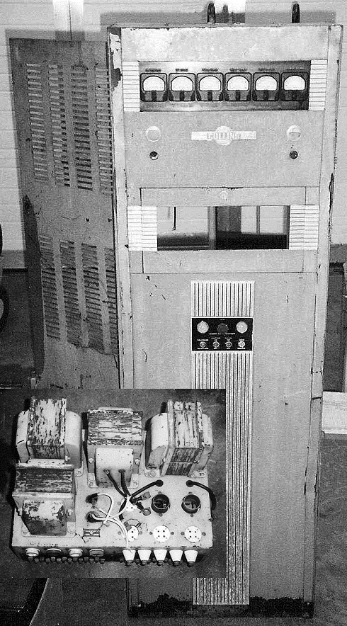
J.B.’s Restoration Shortly after joining the Collins Radio Company in 1959, I met Jim Wisdom, W5HFK. During the next 40 years, we remained good friends, trading parts and equipment for our radio projects. One day, while visiting Jim’s shack, I spotted a beautiful transmitter cabinet. It was a Collins 30J cabinet all dressed out in its art deco trim. The power supply, modulator, and RF assemblies had long since been removed and were gone. After twisting Jim’s arm a bit, the cabinet was proudly loaded onto my truck for the trip home. Inside the cabinet was built a legal limit “no tune” amplifier along with its power supply and control cables. Later, another friend wanted the amplifier, and by now, Jim had dreamed up a project which needed the cabinet. So the cabinet went back to Jim, but his project didn’t require the meter panel and it remained with me. About that time, my interests turned to another prewar transmitter, the 30W. After reading Ed Marriner’s article in CQ magazine, August 1965*, the idea of duplicating the 30W was born, and the collection of parts for the project began immediately. But that’s another story. While searching the classified ads in ER, I met Gary Halverson, WA9MZU. Our telephone chat started with a general inquiry about parts, and it was soon apparent that Gary was a serious collector of Collins equipment and its associated history. Gary was looking for a meter panel for his 30J and was surprised to find one in my spare parts box. Later, Gary spotted a 30J “parts” radio in the ER Classified ads. The cabinet contained the 122C Output Network needed by Gary’s 30J, the 80Z meter panel, and the 401N2 Power Supply. My wish for a 30J was fulfilled through Gary’s generosity. It remains one of my prized possessions. The 30J arrived in a few weeks and restoration started immediately. The cabinet was completely stripped of its trim, cable harness, meter panel, and assemblies. Unfortunately the cabinet had sustained a heavy blow on the top rear corner of the cabinet. The metal was wrinkled and compressed downward. A local auto body shop was able to raise the corner with a “Porta Press”. “Bondo” was added to the wrinkles and then sanded smooth. After several attempts the cabinet was sprayed with Saint James grey paint and left to wrinkle in the hot Texas summer sun. The plate transformer and chokes were cleaned and given a fresh coat of grey enamel paint along with the power supply chassis and assembly. Part of the art deco trim was missing from the cabinet. A local machine shop was able to machine the missing parts using the existing parts as a template. Glass was cut at the local hardware store to fit the missing door and meter windows.
J.B.’s Find Before the Restoration Began
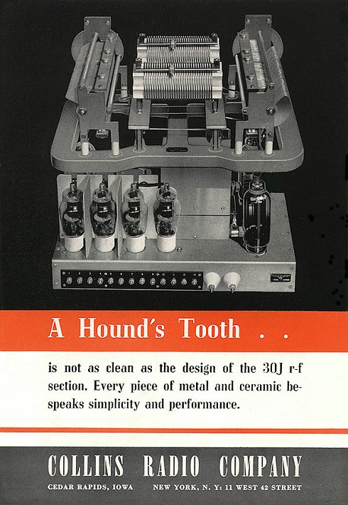
 My attention turned to reproducing the missing 10Y R.F. Unit. Fortunately, the March 1938 issue of QST Magazine contained a picture of the 10Y RF Unit and the 122C Network assembly. The caption: “ A Hound’s Tooth . . . is not as clean as the design of the 30J r-f section. Every piece of metal and ceramic bespeaks simplicity and performance” (see the previous picture in the 3/38 QST ad). By changing the 7000B, 131C exciter coils, and the 130B output coil units, the transmitter could be placed on any frequency between 540 Khz and 60 MHZ. The 10Y tube line up started with the Collins C100 oscillator, followed by two 807’s (or 6L6’s) buffer/multiplier stages, which drove parallel 807’s. The final amplifier tubes were Collins C101A’s also known as Amprex HF100’s. Later designs (such as the 10Y-12) phased out the Collins tubes using instead, the 802 for the oscillator and push-pull 813s in place of the C101 finals. Unfortunately none of the original 10Y assemblies appear to have survived today, but a few 10Y-12 assemblies have been sold on eBay.
New RF Deck Shown in September, 1939 QST Ad
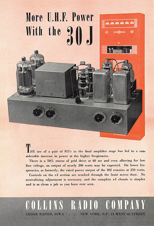
My 30J had been found is a salvage yard in Philadelphia, PA. A call was again placed to the previous owner to see if it was possible for him to return to the salvage yard to search for the missing 10Y RF unit and the 9RD modulator. But it was winter time in Philly and the trip would have to wait for spring. Experience gained from the 30W project revealed that reasonable dimensions can be scaled from a photograph provided it is possible to measure a few dimensions of known parts used on the assembly. With that in mind, a layout of the 10Y was begun on drafting paper. The chassis was viewed as a flat piece of metal and drawn to scale. Parts locations were then measured from the photo and scaled to fit the drawing. Gradually, the drawing began to take shape. Spring brought the much anticipated call from PA. The 10Y and 9RD assemblies had not been found. However, a set of 7000 series coils was found along with the missing glass for the cabinet. It was determined that the coils would not work in Gary’s 10Y-12 RF unit. Again, my project gained another piece of the puzzle and the coil assemblies greatly enhanced the layout effort. The chassis was finally punched and folded in my shop and the wiring began. The oscillator circuit was originally wired for the Collins C-100D tube. The tube worked well when used with the large Collins 2C crystals. With surplus crystals, the oscillator performance was marginal at best. The decision was made to modify the circuit to use a 2A5 tube (this modification was recommended by Collins for users of their 40DA broadcast transmitter exciter). The rest of the circuits were wired and soon 45 ma. of grid current was indicated for the HF-100 finals on 160 meters. At this time, the 401N Power Supply was completely tested. All of the power supplies on the 401N chassis functioned perfectly when powered up, needing only a good cleaning and paint. Although these components have been in the salvage yard enduring the rain and cold for many years, they functioned as well as the day they were removed from service. Gary’s 122C Tuning Network was disassembled and the aluminum casting was duplicated. Because all of the other parts were in hand, they were easily fabricated in my shop. The dial assemblies were another matter. But, luck was with me and I found exact duplicates in a Collins built test set for sale at a local surplus outlet. The original 122C was reassembled and soon found its place in Gary’s 30J. By now, more than two years had been invested in the project and it was set aside for a rest. However, my interest was immediately revived when Gary called to report that another 30J had surfaced in Massachusetts. This 30J had the 9RD modulator intact and the cabinet was mechanically in good shape. Very little time was wasted in making a deal for the transmitter. Arrangements were made with a local amateur in Massachusetts to bring the 30J with him to Dayton (for a little gas money) and my good friend John Orahood brought it back to Texas on his return trip. This time a different approach was used to refinish the cabinet. A business which powder coats race cars and motor bikes was located. They agreed to strip the cabinet and powder coat the cabinet. The cost was double since the cabinet had to be painted twice (smooth finish on the inside and wrinkle finish on the outside). A color which was a close match to the original paint was chosen. The total cost was about $100.00. Many Collins collectors are surprised to find the 30J cabinet painted ‘Machine Grey’ rather than ’St. James grey’. All of the 30J cabinets that I have owned were painted in ‘Machine Grey’ by Collins. However, the 30J-18s that I have seen are painted ‘St. James Grey’. Unfortunately, one of the audio transformers was missing from the 9RD Modulator. This transformer has a distinct shape. Again, a choke (with the proper shape) was found in the “old Collins test set”. The choke was placed in a freezer for a few days. The potted choke slipped out of its case with gentle tapping on its aides. Tar melted off the old choke coil was used to pot the replacement transformer. All of the main assemblies were now present and working. Only the final amplifier coils were missing. Friends tell me that my backside is my most recognizable attribute at the flea markets. That’s because experience has proven that the most needed parts are always found in the cardboard boxes under the tables. The coil forms used in the 130B coils are different from those made by National or Hammarlund. They are distinctly Collins and are difficult to find. A pair of these forms were found in a pasteboard box at a hamfest in Belton, Texas. The slider assemblies needed to adjust the number of turns on the coils were fabricated and mounted to the coil forms along with the banana jacks. The 30J restoration is now complete and all of the assemblies mounted in the cabinet.
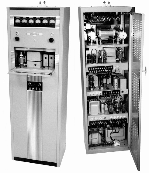
J.B.’s 30J After Restoration (Jay Miller photo credit)
Hard to believe it is the same unit
Will it work???? The frequency of 3870 KHz was chosen. Luckily, a 1935 KHz crystal was found in the junk box. Out came the old Measurements Model 59 grid dip meter and the work began. The oscillator started up OK and the doubler, buffer, and drivers dipped. Let’s see; “Yes, the final grids peak up and now, there is 40 ma. indicated on the grid meter”. The final neutralization was rechecked and is holding just fine. Now, for the moment of truth: plate voltage is applied to the final amplifier. The power supply hums from the heavy load and the plate current meter pegs at 600 ma. The final tuning and loading capacitors are frantically turned, but no dip was present. The transmitter is quickly shut down and the output network is inspected again. But all seems fine here. The grid tuning capacitor was found to be setting at minimum capacitance. Removing 6 turns from the final grid coil moved the capacitor setting to half-mesh at resonance. Again, the plate supply was turned on with the same result: no plate dip. By process of elimination, it was discovered that one of the HF-100 finals was shorted. That fixed, I started removing and adding turns to the final coils without results. A quick e-mail was sent to Gary enquiring about the number of turns on the 80 meter output coil in his 30J. Gary confirmed the number of turns on my final coils were correct. About this time, a frequency counter was connected to the final grids. What’s this? 5805 KHz? My trusty old grid dip meter had let me down! The frequency “doubler” was a frequency “tripler” all along. The doubler was retuned to 3870 KHz. But now, the final grid coil had too few turns. The grid coil was rewound and tuned to 3870 KHz. Wearily, the plate supply is switched on. This time, the final is dipped and loaded to 300 ma. without difficulty. The RF current meters indicate about 1 amp each into a 360 ohm load. Tuning is smooth and there is no indication of parasitic oscillations. AM with the 30J There were two microphones in my collection which have the proper connector for the 9RD modulator. One is the ever popular D-104S and the other, an Electro Voice 638. The Electro Voice was tried first, then the D-104. Both worked well, driving the modulator current upward to 250 Ma. The D-104 sounded tinny while the 638 had a more natural sound in the monitor. Now, let’s connect the antenna. “WA9MZU…WA9MZU…WA9MZU do you copy? This is W5EU standing by!!
Two incredible restorations and a wonderful 30J to 30J contact – Success!
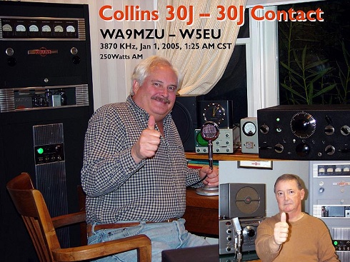
Editor’s Note: The first 30J to 30J contact in probably 50 years was established between W5EU and WA9MZU New Years 2005 on 3870 kHz. Both signals were Q5 with each 30J running 250 watts. Gary currently holds the call sign K6GLH.
* See the Ed Marriner story in ER #187– – – – – End of Article – – – – –
- CCA COLLINS HISTORICAL ARCHIVES
- The Pre War Years
- 150 Series Transmitter
- 2A, 2B AND 2C TUNERS (ATU)
- 30FX Transmitter
- 30FXB Transmitter
- 30FXC Transmitter
- 30FXR Transmitter
- 30J Transmitter
- 30W Transmitter
- 32 A/B Transmitter
- 32F Transmitter
- 32G Transmitter
- 40A/B Transmitter
- 45A Transmitter
- 4A Transmitter
- Bulletin 100
- Bulletin 101
- Bulletin 105
- Bulletin 200
- Bulletin 200A
- The Lost Decade
- The War Years
- Post War Broadcast / Commercial
- The Black Boxes
- The Grey Boxes
- The “S” Word or Solid State