45A Transmitter
COPYRIGHT 2012 CCA
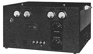
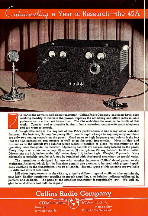
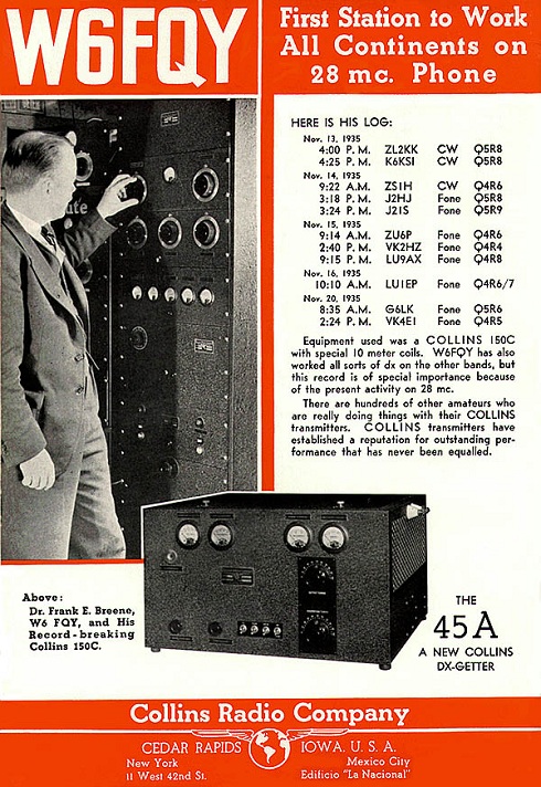
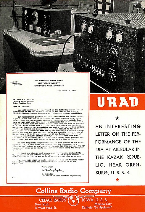
THE COLLINS 45A TRANSMITTER The 45A was perhaps one of the most popular transmitters from the mid to late 30′s. While floor standing transmitters were the norm for medium powered CW transmitters, the 45A was a sharp looking self-contained desktop transmitter running 120 watts CW, 40 watts phone. It measured 21″W x 15″D x10″H and weighed in at a mere 130 pounds. Installation involved simply connecting AC power, a key and or microphone, and the antenna. Promoted as a powerful yet compact desktop transmitter (“a real high-powered baby” — Nov. ’35 QST), it was sold to amateurs, commercial users and police departments.
Early Version of the COLLINS 45A TRANSMITTER
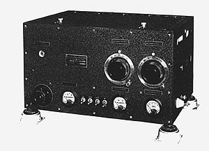
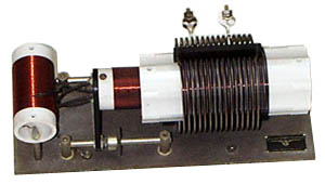
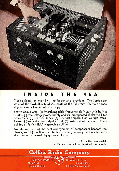
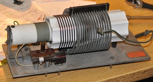
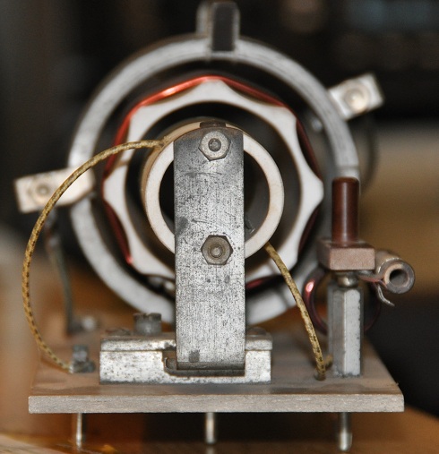
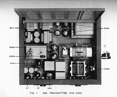
The 45A was a collection of pioneer works publicized in trade magazines of the day. For example, it featured high performance grid modulation, the subject of an article Art Collins published in QST magazine in April of 1935. In the original 1935 model, the tube lineup was a Collins C100A driving a 46 buffer, driving an RK-23 which in turn either drove an 830 multiplier, or the C201 final. A later (1937) model replaced the C100A oscillator with a 6L6 and the final with a 211H (a 211 with a plate cap). Rapid frequency change was accomplished by swapping out two plug-in frequency change assemblies. The first was an “interchangeable frequency shift unit”, an aluminum module that housed the crystal, the oscillator tank coil, and an option multiplier coil. Banana pins mounted on its bakelite bottom provided the electrical connections to the main chassis. The second was the final tank assembly which contained the driver coil cleverly positioned partially inside the final tank coil to do double duty as an inductive neutralization element as a legal workaround to the capacitive neutralization workaround. A rack and pinion provided the adjustment means for obtaining the correct amount of inductive coupling. An output coupling coil wound with ribbon wire (a modified EF Johnson coil) was positioned on the outside of the final tank coil. The entire assembly was mounted on a Mycalex base approximately 4″ by 6″ fitted with banana plugs on the bottom, which mated with a mirroring Mycalex plate mounted on standoffs above the chassis.
Unique 45A Inductive Neutralization – Tank & Driver Tuning Assembly
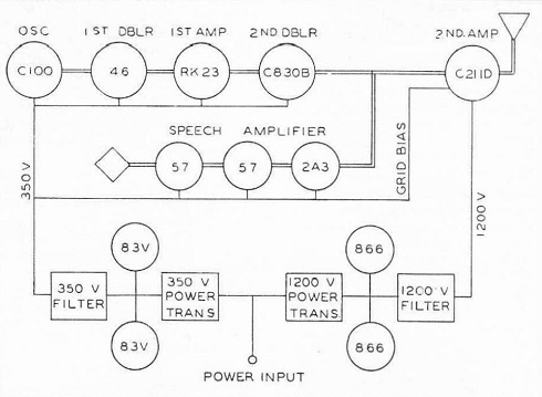
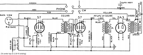
45A Condensed Specifications: (from September 1935 Collins Signal) POWER OUTPUT: 40 watts telephone-125 watts telegraph. FREQUENCY RANGE: 1500 kc. to 30,000 kc. Unless otherwise specified, quotations include frequency units for one band only. RADIO FREQUENCY TUBES: 1-C-100 oscillator, 1-46 first amplifier, 1-RK-23 second amplifier, 1 – C-830B third amplifier, and 1-C-211D output amplifier. AUDIO FREQUENCY AMPLIFIER: 1-57 input (triode connection), 1-57 inter-stage (triode connection) and 1-2A3 power amplifier. The gain of the amplifier is 60 db. The input transmission level is minus 35 db. This is designed for a crystal microphone. The frequency response is essentially uniform from 40 to 10,000 cycles within plus or minus 1.5 db. MODULATION: Control grid. Modulation capability is 100%. AMPLITUDE DISTORTION: 10% maximum at 90% modulation. POWER SUPPLY: The supply voltage is 110-115 v. 60 cycle a-c. The supply line current is 6.5 amperes for telegraph and 4.9 amperes for telephone operation at a power factor of 87 %. Two power supply units are included. The low voltage supply employs 2 ea 83Vs and a separate 2 section filter. The high voltage supply uses 2-866 mercury vapor rectifiers with a two section choke-input filter network. Heating elements may be supplied at extra cost for the envelopes of the 866s to permit operation of the transmitter at zero or below temperatures. NOISE LEVEL: Approximately 55 db below output level. DIMENSIONS: 21 in. wide, 18 in. deep and 12 in. high. WEIGHT: 130 pounds. CABINET: Steel. Black crinkle finish outside. Satin aluminum finish inside. Sides and back are perforated to permit adequate circulation of air. CONSTRUCTIONAL DETAILS: Transformers are oversize, as are also condensers, chokes and resistors. An unusually high degree of mechanical refinement has been accomplished in the construction of the transmitter, making the unit very compact as well as efficient electrically.
* * * * *
Block Diagram
Schematic of the then new unique Grid Modulator for the 45A
To See the 45A Introduction Brochure, Click Here
QST, October of 1935
QST, November of 1935
QST, March of 1936
QST, January of 1937
The very unique Collins Inductive Neutralization method in the 45A
PA Tuning & Neutralization Assembly – End View
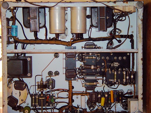
Link to 45A Under-Chassis Photos – Click HereHere are two quick views
– – – – – – – – CCA – – – – – – – –
Note: The images and text used in these pages are copyright 2012 protected, are restored and written by the Collins Collectors Association or its representatives, and may not be used in any other commercial or website applications. They may be downloaded and used privately – not for publication or internet use.
- CCA COLLINS HISTORICAL ARCHIVES
- The Pre War Years
- 150 Series Transmitter
- 2A, 2B AND 2C TUNERS (ATU)
- 30FX Transmitter
- 30FXB Transmitter
- 30FXC Transmitter
- 30FXR Transmitter
- 30J Transmitter
- 30W Transmitter
- 32 A/B Transmitter
- 32F Transmitter
- 32G Transmitter
- 40A/B Transmitter
- 45A Transmitter
- 4A Transmitter
- Bulletin 100
- Bulletin 101
- Bulletin 105
- Bulletin 200
- Bulletin 200A
- The Lost Decade
- The War Years
- Post War Broadcast / Commercial
- The Black Boxes
- The Grey Boxes
- The “S” Word or Solid State
