4A Transmitter
Copyright 2012 CCA
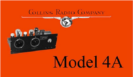
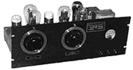 THE COLLINS 4A TRANSMITTER
The 4A was Collins answer to a low-cost basic CW transmitter that the average ham could justify, according to the Collins ads, due to the fact that the combined cost of the components were greater than the purchase price, $58.50 with one set of coils, less tubes. In 1933 this was still not inexpensive.
The 4A was provided with a built-in power supply and used isolantite plug-in coils for each band (sold as an option: a set of two was $5.00). Rated at 25 watts, it used a 47 oscillator driving parallel 46′s. An ’80 was used in the oscillator power supply as the low voltage rectifier, and an 83 as the high voltage rectifier.
QST, December of 1933
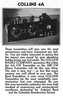 Early models of the 4A had a Bakelite front panel, while later production units had an aluminum panel painted with black wrinkle enamel. The meter was a 0-50 MA Weston in early units, and a Westinghouse model MX in later units.
Gary Halverson and J.B. Jenkins wrote a very good article about this historically important early product of Collins Radio and this article is reproduced below.
Collins Legacies: The 4A Transmitter
By J.B. Jenkins, W5EU and Gary Halverson, WA9MZU Third in a series, this article describes the lowest cost transmitter produced by Collins Radio during the prewar years. While few of these transmitters have survived today, the cute little 4A is perhaps the most common of the prewar Collins transmitters. This article first appeared in our CCA Signal Magazine.A Rig for the Times
The 4A was Collins’ answer to a low-cost basic CW transmitter that the average depression era ham could justify, according to the Collins ads, due to the fact that the combined cost of the components were greater than the purchase price, $58.50 with one set of coils, less tubes. This was a perfect companion for the National SW-3 which sold for under $15.00 at that time. The 4A was provided with a built-in power supply and used isolantite plug-in coils for each band (sold as an option: a set of two was $5.00). Rated at 25 watts, it used a 47 oscillator driving parallel 46’s. An ’80 was used in the oscillator power supply as the low voltage rectifier, and an 83 as the high voltage rectifier.Collins Bulletin D-111
“The 4A transmitter marks the entry of the COLLINS line in the extremely low-priced field. The 4A uses a 47 crystal oscillator and parallel 46’s in the power amplifier permitting an output of 18 to 20 watts on 1.7, 3.5, or 7 mc. The power amplifier is operated on the crystal frequency in each case. Despite its low cost, the 4A embodies the mechanical and electrical refinements found in the larger COLLINS transmitters. A separate power supply is used for the oscillator to reduce frequency ‘chirp’. Standard COLLINS plug-in coils are employed. A single Weston meter is provided with a switching arrangement to read plate and grid currents. The 4A is ideal for an amateur who wants to start out with a minimum investment and yet have a transmitter wich will deliver a high quality C.W. signal. The 4A can also serve as a stand-by transmitter in a high-powered station to be used when full power is not required. Really surprising results can be obtained and amateurs who are accustomed to think in terms of kilowatts can get a great deal of service and amusement form one of these little transmitters”. The above announcement was first made regarding the 4A transmitter in the April-August issue of the COLLINS SIGNAL and only a moderate amount of importance was attached to it at the time. However, during the intervening months this model has proved to be one of our most important products. It has met a very insistent demand for a low-cost, all band CW transmitter which was not burdened by the extra cost and complication of a lot of meters and tuning controls, but, at the same time, was capable of giving consistent performance. We have been very much gratified by the letters we have received from the many amateurs who have purchased this transmitter. Transcontinental schedules are maintained regularly with the 4A’s and several users have reported working Mexico City, Hawaii and New Zealand within the first week or so of operation. Some slight refinements have been made in the circuit of the 4A so that the measured output is now 28 watts on 3,500 and 1,700 kcs., 25 watts on 7,000 kcs., and 13.2 watts on 14,000 kcs. Of course, the outfit is crystal controlled with a D.C. note. We have a few inquiries as to why we do not incorporate the new “universal exciter” in some of our transmitters. The universal exciter is a very clever arrangement, but no advantage is found over our existing 4A and 10B circuits. It should be remembered that the output of the universal exciter is scarely high enough for serious transmission work, unless it is followed by another amplifier, whereas the 4A Transmitter puts out a relatively powerful signal and it also contains dual power supplies, so that no additional equipment has to be purchased. We strongly recommend the 4A Transmitter for the consideration of every amateur who wants the most efficient telegraph transmitter obtainable at a very moderate investment”.The Economy Recovers
Like many depression era products, the 4A was the right product for the time but was quickly forgotten when the economy recovered. The profit margin had to be slim since the unit was labor intensive to build, a liability in an upscale market having more money to spend on higher powered rigs. The various versions of the 4A’s that exist today show the changes of thought that was occurring during its life cycle. Early 4A’s had a Bakelite engraved front panel, while later production units had an aluminum panel painted with black wrinkle enamel and name tags. The meter was a 0-200 MA Weston in early units, and a Westinghouse model MX in later units. Serial tags went from paper labels to brass badges. The 4A was offered through 1935, however promotion efforts ceased when the 30FX was announced.* * * End of Article * * *
QST, December 1933 promotional ad for the 4A with the newly announced 32B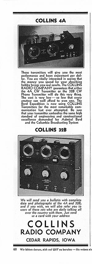 Collins 4A Operating position as it might have appeared in 1933
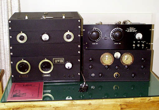 The 4A shown racked up on the left includes the rare 2A balanced antenna coupler and is a later model with the optional metal flanged knobs and later metal badge. The early 4A on the right has the budget Bakelite flange knobs and the early badge. The receiver shown is a rare 1933 RME-9. (Photo, J.B. Jenkins)
More perspective photos of the little 4A can be found at the Rockwell Collins Museum website at:
http://rockwellcollinsmuseum.org/artifact_collection/viewer.php?id=21&v=6
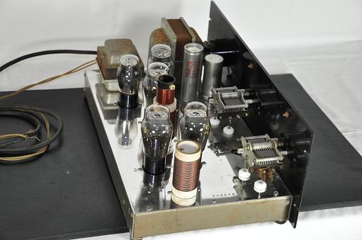
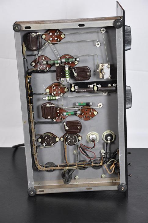
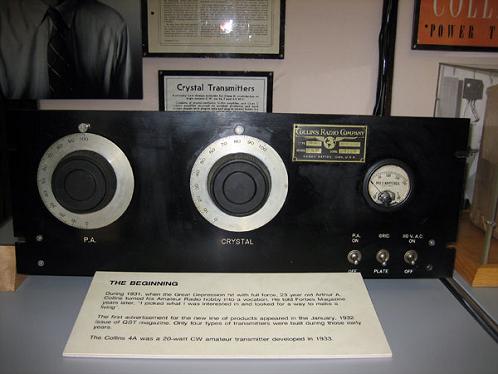 Photos of the internals and chassis details are hard to find on any of the older pieces. The following were submitted by one of our members who is in the process of preserving a very nice original 4A.
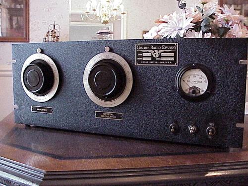
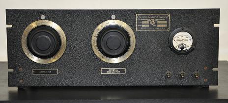 That is a time warp if I ever saw one. This unit is totally original.
– – – – – – – – CCA – – – – – – –
Note: The images and text used in these pages are copyright 2012 protected, are restored and written by the Collins Collectors Association or its representatives, and may not be used in any other commercial or website applications. They may be downloaded and used privately – not for publication or internet use.
- CCA COLLINS HISTORICAL ARCHIVES
- The Pre War Years
- 150 Series Transmitter
- 2A, 2B AND 2C TUNERS (ATU)
- 30FX Transmitter
- 30FXB Transmitter
- 30FXC Transmitter
- 30FXR Transmitter
- 30J Transmitter
- 30W Transmitter
- 32 A/B Transmitter
- 32F Transmitter
- 32G Transmitter
- 40A/B Transmitter
- 45A Transmitter
- 4A Transmitter
- Bulletin 100
- Bulletin 101
- Bulletin 105
- Bulletin 200
- Bulletin 200A
- The Lost Decade
- The War Years
- Post War Broadcast / Commercial
- The Black Boxes
- The Grey Boxes
- The “S” Word or Solid State